Sketch of the Water-Computer
Let's Adore Jesus-Eucharist! | Home >> Varia >> Software Engineering
This article describes a "Water-Computer", a fully-functional, programmable, digital computer that works with a fluid like water, instead of electricity. This water-computer is based on a "water-transistor", and composed of roughly a dozen "modules", each of them roughly the size of a free-standing blackboard. It has no practical application, except for a traveling museum exhibit to teach children how computers work.
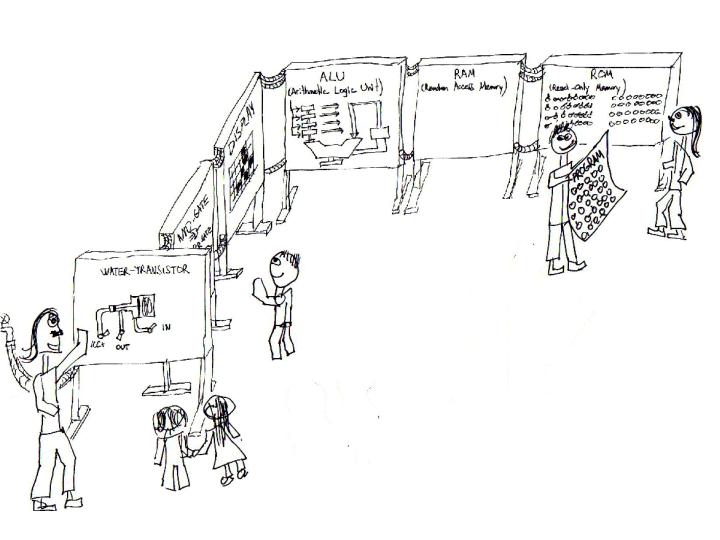
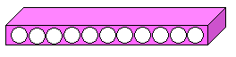
Here is a general view of the Water-Computer (Please! I can't draw. But apart from the silly-looking persons around it, the actual water-computer is technically fairly well represented):
Sketch of the Water-Computer
Something similar has already been done by Mr. Harry Porter, except he used electrical relays instead of "water transistors". It also gives you an idea of what the Water-Computer would generally look like (although by using electricity and relays, the panels of his computer are very much smaller):
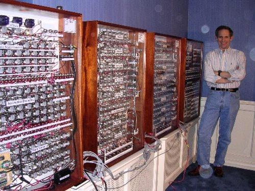
Harry Porter's Relay Computer.
[Harry Porter]
Has anybody ever tried to build a "water-computer"? I am talking here of a real computer, i.e. fully-functional, programmable, digital (not analog; many analog water computers have been built already), and equipped with Input/Output devices. This computer would run on water. Actually, any fluid would do: air, helium, water, oil (attention College students: don't let the word "beer" enter your mind at this stage). One of the advantages of water over say, air, is that with a bit of food coloring you can easily see the "ones" and "zeros".
Of course, this computer would be far too large, slow, unreliable and expensive to be of any practical use (the speed of the CPU would probably be calculated in milliHertz, not megaHertz!). But it might be great to teach children how computers work. In a way, the very essence of teaching is to take difficult concepts, and then make them larger, more tangible, and also to slow them down. A "water-computer" might do exactly that!
With a bit of food coloring in the water, and water transistors made (at least partially) of transparent plastic, you could see the "ones and zeros" be input at one end, then propagate through the various parts of the computer, activating the transistors, being added or subtracted or compared in the ALU (Arithmetic and Logic Unit), being read or written in the RAM (the memory), and eventually being displayed on the "screen" (where each "pixel" could be a colored square that would flip to one white side or the other black side, depending on whether it was actuated by a "one" (i.e. water pressure), or a "zero" (no water pressure).
Children could literally write a tiny program like "2 + 2", then start the "CPU Clock" that pushes, at regular intervals, water pressure driving the whole computer, then run from one panel to the next, tracing the flow of ones and zeros through the computer, leading finally to the screen displaying "4"!
It might make a fantastic traveling exhibit used to initiate children to Computer Science!
If such a digital water computer already exists, please notify me, I want to go see it! If not, read on, you might be able to help make this dream come true!
Just like real computers, the Water Computer would be built up of many, many transistors. These "water-transistors" or "WT" would obviously be different from real transistors that work with electricity.
(Right from the start, I must warn you that the initial design of this "water-transistor" was not made by a certified Engineer. So it might not work. If you see something terribly wrong with this design, like a violation of basic Laws of Physics, please notify me!)
The Water Transistor is conceptually a faucet with three hoses, just like a real transistor. Let's look at a real transistor:
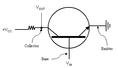
Basic electrical diagram of a transistor.
"All modern digital logic ultimately rests on the fact that a transistor can be
made to operate as a very fast binary switch. In Fig. 1, we show a bipolar
transistor (the circle) embedded in a simple circuit. This transistor has three
connections to the outside world: the collector, the base, and
the emitter. When the input voltage (Vin), is below a
certain critical value, the transistor turns off and acts like an infinite
resistance. This causes the output of the circuit, Vout, to
take on a value close to VCC, an externally regulated voltage
[...]. When Vin exceeds the critical value, the transistor
switches on and acts like a wire, causing Vout to be pulled
down to ground."
[Tanenbaum, Andrew S. Structured
Computer Organization, 4th Ed., p. 118].
This real electrical transistor, when "translated" into a world of faucets and hoses, might look like this, if you cut it length-wise and looked at the cross-section. (Please excuse the ugly diagrams, I would like to have real software like SolidWorks, as well as the skill to use it, but I only have PowerPoint):
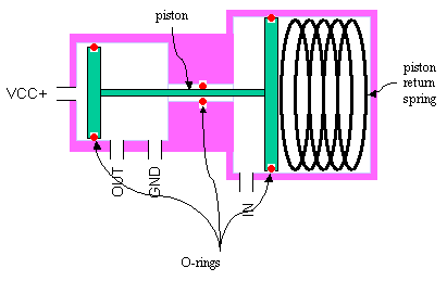
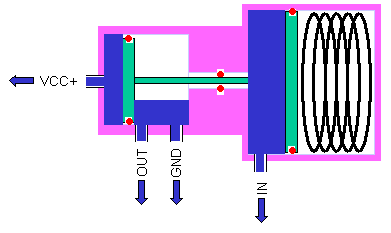
Basic hydraulic diagram of a water-transistor.
It is basically a two-headed asymmetric piston, with enough O-rings to insure water-tightness, various ports to connect the IN, OUT, GND and VCC+ hoses, and finally a return spring.
Let's walk through a typical operating cycle of such a water-transistor (I'll take a "Normally-Closed WT", although it is easy to build a "Normally-Opened WT"). Let's assume we start with the WT in the closed position, i.e. in the "Logical Zero" position:
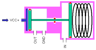
WT in Logical Zero position.
As you can see on that figure, the OUT hose doesn't have any water in it. In other words, the WT is in the "Zero" state. (Don't forget computers use binary logic: Zero or One, True or False, etc.) Now, suppose we want to put it into the "Logical One" state, i.e. we want the OUT hose to have water in it. To do this, we send water into the "IN" hose:
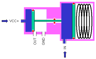
WT starting to change its state from Zero to One.
On this figure, you can see that the water coming in through the "IN" hose is starting to push against the piston. The reason why the IN hose can activate the piston, while the return spring is "pushing against" the piston, is that the piston has a special shape. This is the same principle as for the hydraulic jacks used to lift up your car:
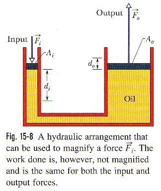
Physical equation from Halliday and Resnick, 6th Ed., p. 328.
Eventually, the piston head on the side of the VCC+ and OUT hoses clears the OUT port. The water can then travel from the VCC+ hose into the OUT hose, and the water-transistor or WT is now in the "Logical One" state. In other words, there is a "One" in the IN hose, which gives a "One" in the OUT hose:
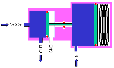
WT in Logical One position.
A final detail in the operating cycle of a WT is that when the piston returns to the "Logical Zero", the OUT hose is automatically reconnected to the GND port. This is just to clear the OUT hose, so it will be ready for the next cycle. If this wasn't done, the WT could block in the "Logical One" in some circumstances.
WT returning to Logical Zero position.
Once we have a working water-transistor or WT, the rest is conceptually simple, and technically somewhat difficult. The reason I say it's conceptually simple, is that from here on, we don't need to invent much: any good Computer Engineering book will tell us how to build AND-gates and OR-gates using WTs, and from there how to build Multiplexers, Decoders, Comparators, Shifters, Adders, ALUs (Arithmetic Logic Units), etc., using AND-gates, OR-gates, etc. From there, we can build RAM, ROM, a CPU, etc., until we have a working computer.
Just to give you a taste how this could be done, here is an AND-gate:
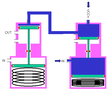
AND-gate built with two WTs.
And here is a conceptual OR-gate:
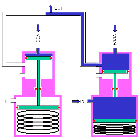
Conceptual OR-gate built with two WTs.
In order to actually work, this conceptual OR-gate would need the addition of two one-way valves (to prevent water pressure coming from one of the WT to propagate out of the Ground of the other WT):
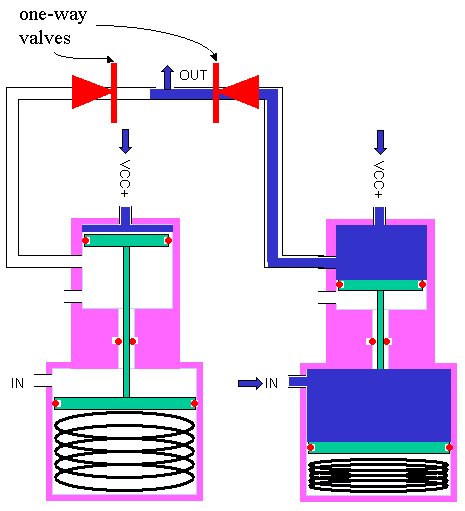
Actual OR-gate, with two one-way valves added.
(Hacker News user "yholio" suggested this modification, over my previous OR-gate implementation. The problem with such an addition of one-way valves is that the output line will not drain out on the next CPU Clock cycle. My previous "solution" required doubling the number of water transistors for the OR-gate (yuck!). Maybe the CPU Clock could, on it's "return cycle", be made to open drainage gates scattered throughout the computer? That would be an ugly implementation kludge, but a separate "Draining Cycle" might actually simplify the architecture, and accelerate the operation of the whole computer. Anyway, I'm still not satisfied with this aspect of the design.)
For the actual computer, we could start with a very simplified version of Tanenbaum's MIC-I (see p. 213).
The reason this project appears to me technically rather difficult is that there are many implementation details that would need to be ironed out. The next part of this article (#5) will focus on a few of these "boring" technical details. If you're not technically inclined, you can skip to section 6 below.
Because computers are made up of very large quantities of transistors, the way the water transistor is manufactured can "make or break" this Water-Computer Project. If each WT is a little bit too expensive, or a little bit too heavy, or a little bit too unreliable, etc., then the huge quantity of WTs will add up and "sink" the project, either because of excessive cost, weight, reliability, etc.
Here are some preliminary design requirements for the WT, as well as some possible directions for manufacturing:
5.1) High Reliability. The WT must not leak in either opened or closed position. It must open and close completely (i.e. not stop halfway). It must not jam.
Possible solutions? To prevent leaking and jamming, I'm guessing high-quality O-rings, well-machined surfaces that won't scrape or cut the O-rings, a filtered and purified fluid (like distilled water), and perhaps a bit of lubricant added to the water (or other fluid) used to operate the Water-Computer. To prevent stopping halfway, we're guessing using a sufficiently high pressure for water input, and a sufficiently strong return spring.
Problems? Drilling the ports into the cylinder will be difficult, because the O-ring on the "OUT" side must not be damaged by sharp edges.
5.2) Low Cost. Since by definition this Water-Computer project will never have any commercial use, costs will have to be very low (income sources will probably be only a few geeks, along with some government grants coming from public museums).
Possible solutions? Keep size down (see #5.3 below). Use COTS (Common Off-The-Shelf) parts, like small transparent plastic hoses used in medical devices. Maybe make the WT out of some kind of polymer (like Delrin), which would keep down the weight, make manufacturing easy (its easier to machine Delrin than High-Speed Steel!), avoid rust, perhaps give some measure of self-lubrication (as for gears made out of Nylon), etc.
5.3) Small Size. If the Water-Computer is to be of a manageable size, each WT must be as small as possible. Smaller sizes, as for real transistors, probably mean lower costs, lower latency for signal propagation, a faster clock, a traveling exhibit which is easier to transport and set up, etc.
What will limit the size? Let's assume we take the smallest standard medical transparent hose that gives us "a reasonable flow" (as for some IV machines). Given that hose's inside diameter (I.D.), we know the piston head on the "OUT" side can't be of a smaller diameter. That I.D. also would seem to determine the piston "stroke" or travel distance, since it needs to clear the output port, of the same I.D. One of the only "free variables" would appear to be the diameter of the "IN" piston head. It has to be big enough to provide the "hydraulic jack" effect sufficient to counter-act the effect of the return spring. The return spring has to be strong enough to "shut-off" the WT, overcome the friction of three O-rings, plus a "safety margin" to avoid jams, compensate for loss of spring resiliency, etc.
5.4) "Gangable". Normally, there will be no reason to have individual WTs. It should be possible to "gang" a large group of WTs, thereby reducing total size, and manufacturing costs.
Possible solutions? It would be nice to be able to "stand-up" these WTs, a bit like cells in a honeycomb, so we could machine them into a large bloc of Delrin. We'd need to find a way of making the ports available otherwise than from the side, or at least minimize the number of sides "occupied" by these ports.
5.5) Ease of Testing, Inspection, Maintenance.
Possible solutions? Maybe the "piston covers" could be made of transparent plastic? If we can "gang" WTs, this would mean we could visually inspect the operation of all WTs fairly quickly. If these "piston heads" were easy to remove, some O-rings could be changed fairly quickly.
What would this Water-Computer look like?
Of course, I can't know before it has been designed! But I'm guessing that it would look a lot like the "poster sessions" they have in trade shows. Each module of the computer (like the RAM, the ROM, the ALU, the "screen") would be a free-standing unit, somewhat like a very thick poster on sturdy legs. These poster-aquariums would be connected by "buses", i.e. hose bundles. (See Sketch of the Water-Computer here above.)
One of the advantages of these poster-aquariums is that they would be two-sided, and partially transparent. One side would be the "Physical" side, showing the actual WTs, and the hoses connecting them (so students could see the "wiring diagram" of the hardware). The other side would be the "Logical" side, showing what that particular arrangement of WTs actually was (like a Shifter, or an Adder, etc.) So students could go from one side of the module to the next, to "toggle" repeatedly from the "Physical" level of abstraction to the "Logical" level of abstraction. Wow! What a great pedagogical trick!
Another advantage of these poster-aquariums is that the "text and graphics layer" would be removable. In other words, no text or graphics would be "burnt-in" the module. It could be printed on a kind of large overhead projector transparency, itself attached to the module. This means we could have localized versions (French, English, Spanish, etc.) of the Water-Computer.
In theory, we could run the Water-Computer on another liquid (like the proverbial beer) or even a gas, but I think water would be the best choice: inexpensive, non-toxic, non-staining, easily dyed, etc.
Whatever the liquid or gas, I would recommend a "double-hull" construction for these modules, to avoid spillage (museums don't like floods!). Normally, all the fluid would be contained in WTs and hoses, but if a leak occurred, it would be caught by the "outer", water-tight hull.
Since everything would be modular, and the connections between modules would be flexible (hose bundles), the traveling exhibit could adapt to many different room layouts. This means it could be set up in smaller (or strangely-shaped) museum or school halls.
I'm also guessing that part of the exhibit would be the actual Water-Computer, but the first part of the exhibit would explain the building-blocks of that computer. For example, one module could be a simple, large water-transistor, which the kids could operate with valves. Once they understood the basic WT, the next module could explain AND-gates and OR-gates, and so on, until they were ready to face the actual computer.
Since ROM for a Water-Computer is simply a standard faucet (if it's closed, it's a Zero, and if it's open, it's a One!), one module of the computer could be just a large array of valves. Programming the computer would just be turning these valves on or off! The programs could be "written" on large perforated-posters (the holes would let the valve handles poke through). Kids could select a "Add 2 and 2" perforated-poster, place it over the ROM module, turn the appropriate valves on and off, and then just run the program! Old fogies would get teary-eyed ("Perforated-posters, just like the perforated cards we had when I started!", etc.).
The CPU Clock would probably be a kind of big piston-clock that would "push" water into all the inputs at the beginning of the cycle, long enough for the "signal" to propagate through all the gates. Then, at the end of the cycle, the piston-clock would "go to ground", since (as far as we can see, anyway) the whole system would need to "drain" out, at least partially, between each clock cycle.
Since (1) children like to manipulate objects, and (2) it's hard to see water go by in a transparent plastic tube, and (3) adding little reflective flakes or any other particle in the water to see it go by would wear down the O-rings and clog the mechanisms, I think there could be little binary-droppers. Scattered here and there in the water-computer, there would be little buttons that would inject food-grade coloring into the water flow. A child, seeing a given group of transistors, could therefore decide to observe how it worked. He'd wait for the next "clock cycle", and inject a few drops of coloring. He could therefore see Zeros and Ones travelling around the water-computer!
Oh, all right, I admit I'm not doing this for the kids. I would have loved to go to such a museum exhibit when I was young!
Do you know of anything similar out there? If not, can you see major disasters in this preliminary description? If not, do you have any more ideas that could make this project even more interesting?
Thanks!
Of course, none of this is new. "Water-Transistors" already exist, under different names like "Hydraulic Relay", "Remote valve", "Wall-Attachment Microfluidic Amplifier", etc. Also, analog "Water-Computers" already exist, and maybe even digital ones too (Please tell us if you know of one!). Here are some references (thanks Michel S., Wayne C., Dave R., Andrew C., for these links):
Fluidic
XOR gate (Paulo Blikstein)
Fabrication
of a Free-Floating Silicon Gate Valve (Papavasiliou, Leipmann, Pisano)
Basic
Logic Valves Series 2L (Camozzi)
Design
of Pneumatic and Fluidic Control Systems (Edward L., Holbrook)
The Research and
Application Survey of Fluidic Amplifier (Yong, Shuxing, Ziguang)
K'Nex Logic
(Mike Gleen)
Fluid
chip does binary logic (microfluidic logic chips; Colorado School of Mines)
Fluid
"Transistor" Circuits (Pure fluid amplifier;
US Army's Diamond Ordnance Fuze Lab)
Fluidics (Wikipedia)
Bernard
Gitton's Liquid Science
Bowles Fluidics
(Douglas St. Clair)
Russian
Water Integrator (i.e. analog water computer)
MONIAC
(yet another analog water computer)
Etc., etc., ...
I don't have the skills to evaluate existing products and designs. Nevertheless, it seems to me that there are some reasons why many of the existing designs might not be appropriate for a Water-Computer:
8.1) Often, the "VCC+" and "Output" or "Input" streams are not at the same pressure. I've seen a few existing devices that were "water-transistors", but which required different pressures. But in a Water-Computer, the "Output" of one WT often becomes the "Input" of another WT.
8.2) Some of these devices don't seem to be able to do work. What would happen if some of these devices had backpressure on their outputs?
8.3) Often, the device's mechanism is not intuitive. In other words, they work, but a kid wouldn't understand why.
8.4) Nanotechnology cannot be used as a pedagogical device. Nanotechnology is cool, but here again, for educational purposes, kids need to see what is going on.
8.5) Cost and size. Some remote valves (a.k.a "water-transistors") really exist and work, but they are very large and expensive, which means the "Water-Computer" could not practically be built with them.
Once again, I'm not a Manufacturing Engineer, so there are just wild guesses.
Basically, everything would be built out of two stocks of Delrin, one roughly shaped like a 2x3 piece of wood lumber, and the other shaped like a broomstick. The "2x3" would be the housing for a rack of WTs:
Delrin 2x3 forming the housing for a row of WTs.
The "broomstick" would be shaped into individual pistons and piston covers fitted into the rack. This is what an individual WT would look like:
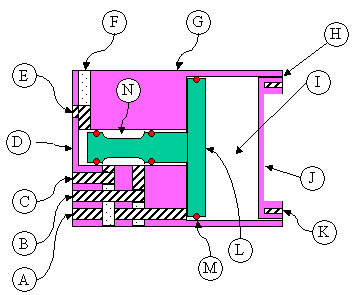
Side view of a WT implementation.
Legend:
A) IN line.
B) GND line.
C) OUT line.
D) Since the housing would be quite thin in this area, we might be able to see
the position of the piston. If not, some more trickery would be necessary for kids
to be able to observe the position of the piston (i.e. the "zero" or the "one"
of the water transistor).
E) VCC+ line.
F) In order to make WT racks "stackable" (to increase transistor density), we
have to make all lines accessible from the rear. I don't know how to do this
without drilling two holes for each line, and plugging one partially, to form a
conduit that "turns" 90 degrees. All lines (IN, GND, OUT and VCC+) are drilled
this way, and have a "plug".
G) The main housing for a rack of WTs.
H) I'm guessing this area would be threaded, so the piston-cap could be screwed
in, and be water-tight.
I) This is where the spring goes, for the Normally-Closed WT. For
Normally-Opened WTs, the IN line would have to go all the way, and enter near
the piston cap. I haven't looked too much into that yet.
J) Piston cap. Hopefully it too (like for D) would be thin enough in this
location, so as to permit visual inspection of WT.
K) Two little holes drilled in piston-cap so we can screw it in and out.
L) The actual piston.
M) All red "circles" are O-rings on the piston.
N) This "thinning" of the piston shaft is what lets the water run out to GND.
I don't know much about CNC-controlled automatic-feed Machining Centers, but I'm guessing the "broomstick" could be shaped into pistons and piston caps fairly automatically, and the "2x3" could be milled, drilled and reamed also fairly automatically.
-----Original Message-----
From: Douglas St.Clair
Sent: 21 novembre 2007 19:11
To: Stefan Jetchick
Subject: Re: My Relay Computer.

I worked with Bowles Fluidics back in the late 1960s and later taught
a seminar on the subject. The devices that Dr. Bowles constructed
were much further advanced than the ones referred to in the article
you referred to.

I remember one consisted of a rocket flight path controller. There
were three relatively small pipes evacuating the main combustion
chamber. That took the exhaust (several thousand degrees and very
high pressure) out to an oscillator consisting of three fluidic
switches. The output of the switches could either be fed back near
where the rocket exhaust left the engine or simply dumped. In normal
(straight flight) operation the three amplifiers fired one after the
other keeping the exhaust gasses going straight. To steer the craft
one amplifier didn't fire back into the exhaust gasses and the other
two deflected the gasses to it's side turning the rocket. Once back
on course the third amplifier was pulsed in rotation again bringing
the rocket back to straight flight. All the control "circuitry" was
also fluidic and also ran off the gas stolen from the main combustion
chamber. The darn thing was accurate, reliable, and ran at the
temperature of rocket exhaust gasses. Try that with your little
poppet valves. :-)

Another application that I found interesting consisted of a large
cast block with a 36 inch window fan blowing in one end and a pair of
36 inch holes on the other side of the block. There were two pieces
of pipe sticking out of the top. When you placed your hand over one
piece of pipe the air blew out of one hole. Cover the other piece of
pipe and the air switched to the other hole. A similar switch was
built to control irrigation in commercial fields.

Interestingly a major problem for fluidic was in understanding where
if fit best. While most pneumatic devices ran at high pressure to
move the valves etc. Fluidic logic ran at much lower pressures - a
few inches of water. However when a valve devices switches it
generally stops the flow and retains the pressure. When fluidic
devices switch they redirect the flow so that the total air flow to
run the logic remains constant. In some cases the total energy
required to run fluidic logic for a day is more than the energy to
supply high pressure air to devices that stop the flow after changing
their state.

There were other problems the most interesting one for me being the
problem of reliability. A fluidic device could be made of almost any
material. High temperature ceramic was used for the rocket
controller. On a long duration space mission should the fluidic
computer "fail" the chances were it was do to a blocked port and it
could be taken apart and cleaned, then returned to service. On the
contrary an electronic or pneumatic valve computer failure required a
spare part. Ergo the fluidic computer (with repair) was probably able
to be run and maintained without spares for ever. This morphed into
the belief they were more reliable and yet there were cases where the
MTTF was so short it was impossible to complete even a short mission
without a failure.

Douglas St. Clair
Tir na nOg
Wilton, NH USA
Let's Adore Jesus-Eucharist! | Home >> Varia >> Software Engineering